ECN, PFC and CNP the drivers of RoCEv2 Ethernet
I often discuss AI data centre technologies such as RoCEv2, ECN, PFC and CNP from a high-level perspective.
But what does it actually look like when you have to implement them?
Does every switch along the path need to support these technologies? How does the network detect congestion? How is the sender notified to slow down before packets are dropped? Where does ECN fit into the packet journey, and when does PFC step in?
Understanding the theory is one thing. Understanding how to build a lossless Ethernet fabric is another.
Which is why I use this simple methodology: study the theory, lab and blog to study a piece of technology.
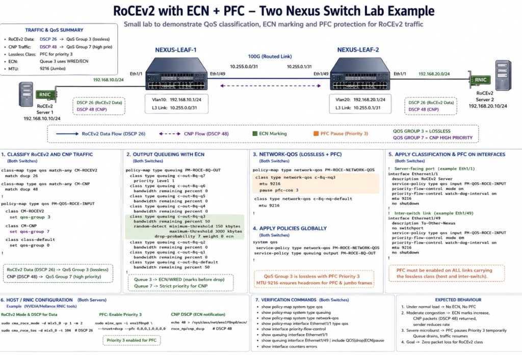
In this example lab diagram, I walk through a simple end-to-end Cisco NX-OS lab using two Nexus switches acting as the AI Ethernet fabric, connected to two RoCEv2-enabled GPU servers performing light small language model training. We build the complete packet journey from start to finish, covering the configuration of QoS, ECN, PFC and CNP, and see how they work together to keep AI traffic flowing efficiently without packet loss.
All configuration are performed on all traffic path.
Please note: These feature are only supported on Nexus 9000 Cloud Scale platforms (FX3, GX, GX2, H-series and newer)
It’s best to learn PFC, ECN, CNP, RDMA and RoCEv2 together in Ethernet AI fabrics as they are highly dependent on each other.



Leave a comment