Introduction
For me one of the most interesting aspects of AI Infrastructure is the backend network. There are many technologies and acronyms that are continuously mentioned such as RDMA, RoCEv2, PFC, ECN, CNP and DCQCN. Initially it can become quite confusing because most of these technologies are normally explained independently. However the key component here is to understand why we actually need them and how they all work together.
The starting point is actually not RoCEv2 or PFC. The starting point is the AI workload itself.
When we are using a single GPU, there may not be any requirement for that GPU to communicate with another GPU over the backend network. However once we start distributing an AI workload across multiple GPUs, especially across different physical servers, those GPUs need to exchange information with each other.
This could be caused by different types of parallelism such as Tensor Parallelism, Data Parallelism, Pipeline Parallelism or Expert Parallelism. Subsequently the backend network becomes part of the AI workload itself.
This is where RDMA becomes extremely important.
Why are GPUs communicating with each other?
A modern AI workload may not necessarily fit or run efficiently on a single GPU. A large model may need to be distributed across multiple GPUs because of GPU memory capacity, compute requirements or simply because we want to improve performance.
For example Tensor Parallelism may split parts of the same model calculation across several GPUs. Expert Parallelism may place different experts across different GPUs. During distributed training we also have collective communication operations such as AllReduce, AllGather and ReduceScatter.
The important point is that these GPUs are not independently performing work. They are continually exchanging information with each other.
If those GPUs are inside the same physical server, technologies such as NVLink or NVSwitch may provide this communication internally. However once the communication crosses between physical GPU servers, it needs to traverse the backend network.
Subsequently we can represent the overall process as:
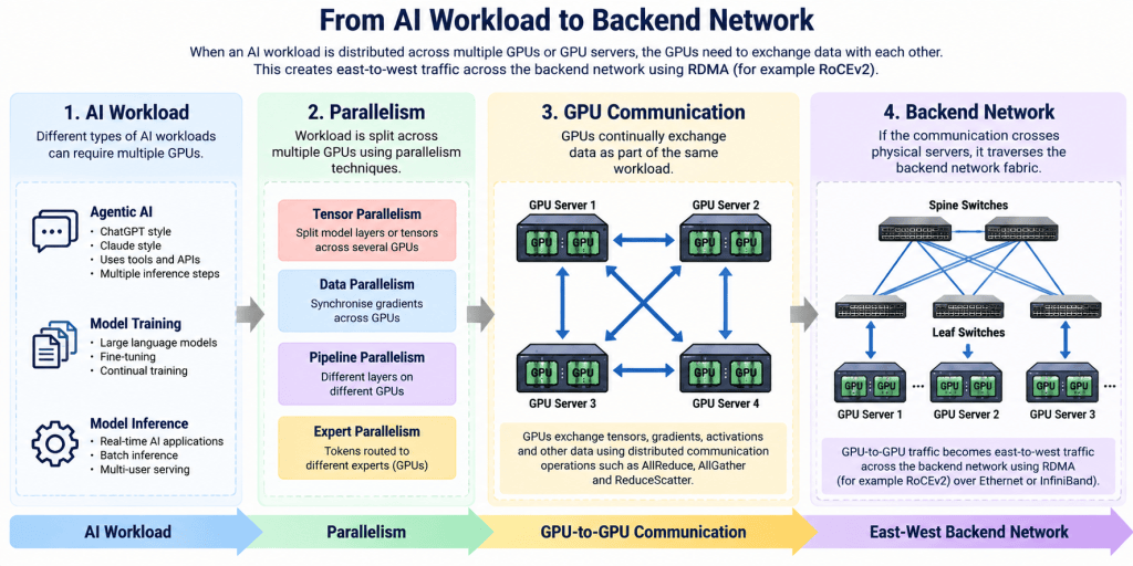
This is where the network architecture becomes extremely important. If one GPU is waiting for data from another GPU before it can continue processing, any network congestion, latency or packet loss can directly impact the performance of the workload.
What about Agentic AI?
Another area where this becomes particularly interesting is Agentic AI.
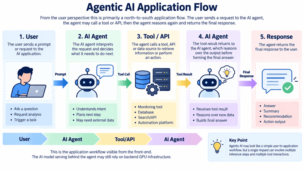
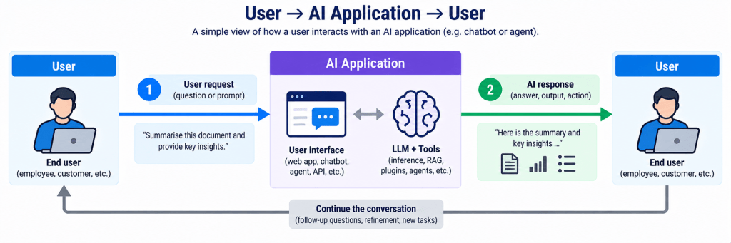
When people think about something similar to ChatGPT or Claude, it can appear to be a relatively simple north-to-south application. The user sends a prompt towards the AI system and eventually receives a response back.
However this is only what we see from the application side.
Behind that interface there is still a Large Language Model performing inference. If that model is large enough that it has been distributed across multiple GPUs or multiple GPU servers, the backend network may still be heavily involved.
For example a user may ask an AI agent:
“Check the current state of my network, identify the fault and recommend the next action.”
The Agentic AI application may first perform inference to understand the request. It may then call a monitoring tool or API, retrieve some information and send that information back into the model for further reasoning. The model may subsequently perform another inference operation before returning the final answer.
From the application perspective this may look something like:
However behind the AI agent the model inference may look more like:
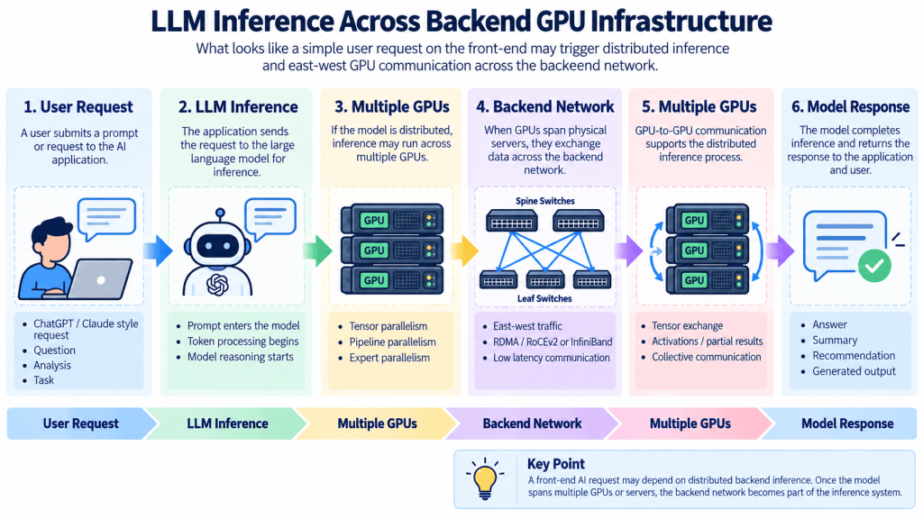
If Tensor Parallelism, Pipeline Parallelism or Expert Parallelism is being used across physical GPU servers, every inference operation may generate east-to-west traffic across the backend network.
This is an important distinction for me. Agentic AI may appear to be a north-to-south workload from the user perspective, however the model serving infrastructure behind it can still be heavily east-to-west.
Subsequently the backend network may become part of the inference system itself.
What is RDMA?
RDMA stands for Remote Direct Memory Access.
The purpose of RDMA is to allow data to be transferred between the memory of two systems with extremely low latency and with minimal involvement from the CPU and traditional operating system networking stack.
In AI Infrastructure we often refer to this as GPU-to-GPU communication. However technically the GPU itself is not simply generating an Ethernet packet and sending it directly into the network.
The GPU server contains a high-performance RDMA capable Network Interface Card, normally referred to as an RNIC.
With technologies such as GPUDirect RDMA, the RNIC can transfer data directly between GPU memory across the network without requiring the normal data path through CPU system memory.
So logically we may think of the communication as:
GPU 1 > GPU 2
However the actual path is closer to:
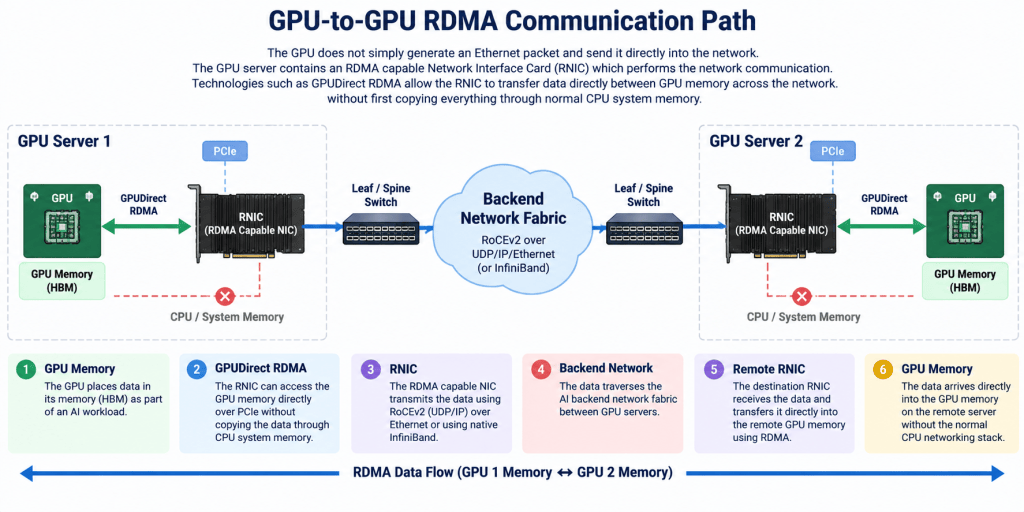
The purpose is simple. We want the GPUs to exchange information as efficiently as possible.
For distributed AI workloads this becomes particularly important because the GPUs can be highly synchronised. One GPU may need information from another GPU before the next stage of processing can continue.
Why does RDMA need a different type of network?
RDMA requires extremely low latency and very low packet loss.
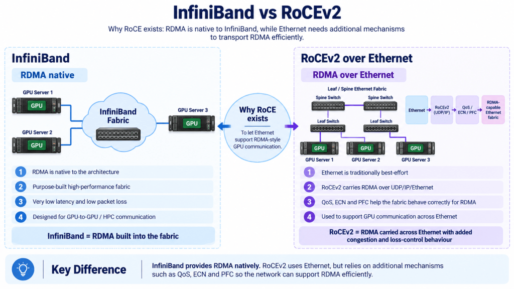
This is one of the reasons InfiniBand has traditionally been heavily used for HPC and large scale AI environments. RDMA is native to the InfiniBand architecture and InfiniBand was fundamentally designed around this type of high performance communication.
Ethernet comes from a completely different background.
Traditional Ethernet is effectively best-effort networking. The network will attempt to deliver the packet, however if congestion occurs and a switch buffer becomes full, packets can be dropped.
For normal enterprise networking this is generally not a major issue. TCP can detect the missing packet and retransmit it.
However in a distributed AI environment this behaviour is not ideal.
Imagine multiple GPUs continually exchanging information as part of the same workload. If packets are dropped and have to be retransmitted, this introduces additional delay. That delay may cause other GPUs to wait before they can continue processing.
The key component to remember here is that the GPU is an extremely expensive compute resource. We ideally want the GPU performing useful compute rather than waiting for network communication.
Therefore traditional best-effort Ethernet behaviour is not particularly suitable for high performance RDMA traffic.
This is where RoCEv2 comes into the picture.
What is RoCEv2?
RoCE stands for RDMA over Converged Ethernet.
In very simple terms RoCE allows us to transport RDMA traffic across Ethernet.
RoCEv2 is the routed version and carries the RDMA communication over UDP/IP. This allows us to use a traditional Layer 3 Spine and Leaf Ethernet fabric and still provide RDMA communication between GPU servers.
At a high level the traffic path can be represented as:
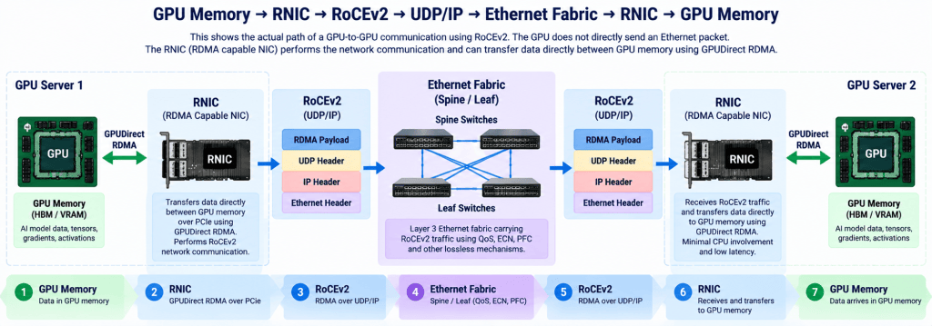
This is extremely useful because Ethernet is already widely deployed inside modern data centres.
However the key component to remember here is that RoCEv2 itself does not make Ethernet lossless.
RoCEv2 gives us the ability to transport RDMA over Ethernet. The underlying Ethernet network still has its normal best-effort behaviour.
Subsequently we need additional technologies to make Ethernet behave in a way that is more suitable for RDMA.
This is where technologies such as QoS, ECN, CNP and PFC become important.
For me RoCEv2 is effectively taking Ethernet and adding the additional mechanisms required so that it can provide the low-loss and low-latency characteristics expected by RDMA. The purpose of RoCEv2 is essentially to emulate a InfiniBand network fabric.
I sometimes think of this as effectively band-aiding Ethernet for RDMA. There is nothing inherently wrong with Ethernet. It was simply designed around a different networking model.
Understanding congestion inside the Ethernet fabric
Before discussing ECN and PFC we need to understand what actually happens when congestion occurs.
Imagine two GPU servers connected across an Ethernet backend fabric. GPU Server 1 is sending RoCEv2 traffic towards GPU Server 2.
Under normal circumstances the packet enters the switch, is placed into the appropriate queue and is transmitted towards the destination.
Now imagine several GPU servers are all sending traffic towards the same destination at the same time.
For a short period, more traffic may enter a switch than the outgoing interface can physically transmit.
The switch does not immediately drop all of this traffic. It temporarily stores packets inside a buffer or queue.
Therefore we effectively have:
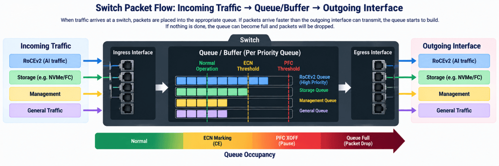
If packets leave the queue as quickly as they arrive, there is no problem.
However if packets continue arriving faster than they can leave, the queue occupancy begins to increase.
Eventually, if nothing is done, the buffer becomes full.
Once the switch has no more buffer space available, the next packet has to be dropped.
For RoCEv2 traffic this is exactly what we are trying to avoid.
This is where ECN becomes important.
What is ECN?
ECN stands for Explicit Congestion Notification.
For me the easiest way to understand ECN is that the switch is warning us about congestion before it actually has to drop the packet.
The switch monitors the occupancy of the queue. Once the queue reaches a configured ECN threshold, the switch begins marking packets.
The packet is marked with:
CE – Congestion Experienced
The important point here is that the packet is still forwarded.
The switch is effectively saying:
“Congestion is starting here. I am still forwarding this packet, however the sender needs to slow down.”
The packet then continues through the network towards the destination RNIC.
This is quite different from waiting until the buffer becomes completely full and simply dropping packets.
The network is attempting to react before packet loss occurs.
What is CNP?
Once the destination RNIC receives an ECN marked RoCEv2 packet, it needs a way of informing the source RNIC that congestion has occurred.
This is where CNP is used.
CNP stands for Congestion Notification Packet.
The destination RNIC receives the ECN marked packet and generates a CNP back towards the source RNIC.
The complete process becomes:
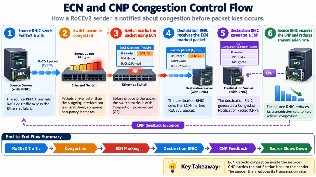
For me this is the simplest way of understanding the relationship between ECN and CNP.
ECN identifies and signals congestion inside the network. CNP carries that congestion information back towards the sender.
The source RNIC can subsequently reduce the rate at which it is transmitting RoCE traffic.
You will also hear the term DCQCN when discussing RoCEv2.
DCQCN stands for Data Center Quantized Congestion Notification. At a high level DCQCN provides the congestion control behaviour used by the sender to adjust its transmission rate based on ECN and CNP feedback.
Initially I would not overcomplicate DCQCN.
The key component is:
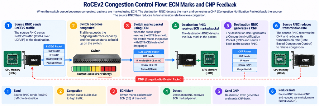
Ideally this happens early enough that the queue starts to drain before packet loss occurs.
However there is another question.
What happens if the traffic is arriving so quickly that ECN and CNP cannot react quickly enough?
This is where PFC becomes important.
What is PFC?
PFC stands for Priority Flow Control.
To understand PFC it is useful to first understand the concept of Ethernet PAUSE.
Ethernet can send a PAUSE frame towards an upstream device telling it to stop transmitting temporarily.
The problem with normal Ethernet PAUSE is that it can stop the entire link.
This is not necessarily what we want.
A physical interface may be carrying RoCE traffic, management traffic, storage traffic and perhaps other application traffic.
If only the RoCE queue is congested we do not necessarily want to pause everything.
PFC improves this by allowing the pause to operate on a particular Ethernet priority.
In a RoCEv2 environment we normally classify the RoCE traffic into a particular QoS priority.
If the buffer associated with that priority becomes dangerously full, the switch can send a PFC pause towards the directly connected upstream device.
This is normally referred to as:
PFC XOFF
What does PFC XOFF mean?
For me the easiest way to remember this is:
XOFF = Stop
Imagine Switch 2 is receiving RoCE traffic from Switch 1.
The RoCE queue on Switch 2 is becoming dangerously full and is approaching the configured PFC threshold.
Switch 2 sends a PFC XOFF message towards Switch 1 for that particular Ethernet priority.
Effectively Switch 2 is saying:
“Stop sending this priority temporarily.”
Switch 1 subsequently pauses transmission of that RoCE priority towards Switch 2.
Other priorities on the same interface may continue transmitting.
This gives Switch 2 time to drain the congested queue.
The process can be represented as:
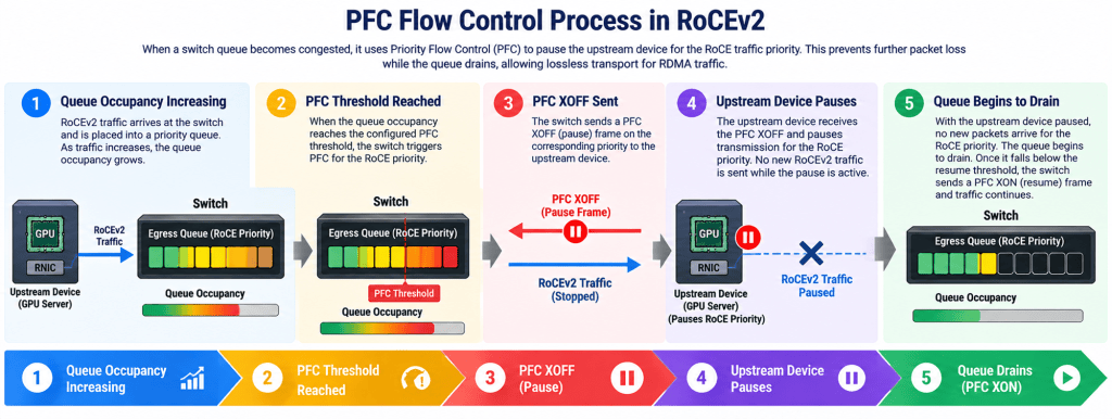
The important component to remember here is that PFC operates hop-by-hop.
The congested device sends the PFC pause towards the directly connected upstream device.
Obviously we cannot leave the traffic paused forever.
Once the queue has drained sufficiently the switch needs to tell the upstream device that it can begin transmitting again.
This is PFC XON.
What does PFC XON mean?
Again for me the easiest way to remember this is:
XOFF = Stop
XON = Start again
Once the queue has drained below the required threshold, the switch sends PFC XON towards the upstream device.
The upstream device can subsequently resume transmitting the RoCE priority.
The overall process therefore becomes:
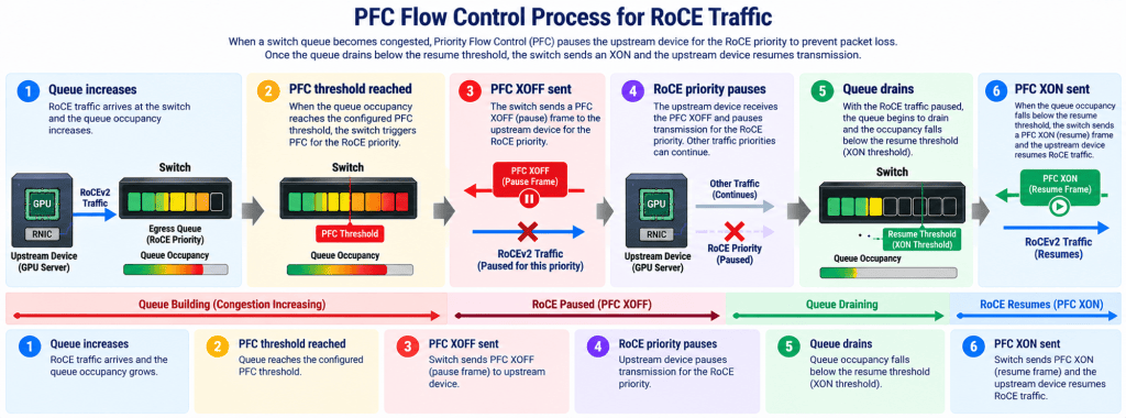
This helps prevent the RoCE queue from overflowing and dropping packets.
Why do we need both ECN and PFC?
Initially this can become confusing because both ECN and PFC appear to be solving the same problem.
However they perform different roles.
ECN and CNP are primarily there for congestion control.
The purpose is to detect congestion before packet loss occurs and tell the sender to reduce its transmission rate.
PFC is there as a protection mechanism.
If congestion continues to increase and the queue approaches a point where packet loss may occur, PFC temporarily pauses the traffic class.
For me the easiest way to remember the difference is:
ECN + CNP = Congestion Control
PFC XOFF/XON = Loss Protection
Ideally ECN and the sender rate control should deal with the majority of congestion events.
We do not want the network continually relying on PFC pauses.
PFC is extremely useful, however repeatedly pausing traffic is not necessarily an indication of a healthy congestion control design.
The goal should be for ECN and the sender to react before the network continually reaches the PFC threshold.
The complete RoCEv2 packet journey
Once all of the technologies are understood individually, the complete packet journey becomes far easier to understand.
Imagine we are running a distributed AI workload across multiple GPU servers.
The workload may be using Tensor Parallelism. GPU Server 1 has completed part of the calculation and needs to send information towards GPU Server 2.
The source GPU provides that data towards its local RNIC.
The RNIC transmits the data using RoCEv2 across the Ethernet backend fabric.
Under normal circumstances the packet travels through the network and arrives at the destination RNIC without any issues.
Now congestion starts.
The egress queue on one of the switches begins to increase because packets are arriving faster than the outgoing interface can transmit them.
Once the ECN threshold is reached, the switch marks the RoCEv2 packet with Congestion Experienced.
The packet is still forwarded towards the destination RNIC.
The destination RNIC receives the ECN marked packet and generates a CNP back towards the source RNIC.
The source RNIC receives the CNP and reduces its transmission rate.
Hopefully this is enough to reduce the congestion and allow the queue to drain.
If the queue continues increasing and reaches the PFC threshold, the switch sends PFC XOFF towards the upstream device.
The upstream device temporarily pauses the RoCE priority.
Once the queue has drained sufficiently, the switch sends PFC XON and transmission resumes.
Subsequently the complete process becomes:
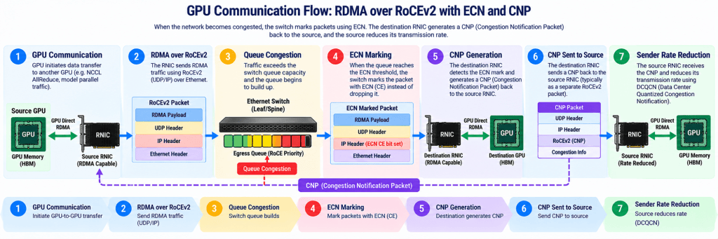
If congestion becomes more severe:
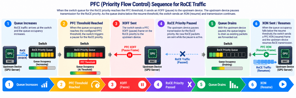
For me this is where all of the individual technologies start to make sense.
Does every switch need to support this?
Another important component is the complete end-to-end traffic path.
If RoCE traffic crosses several switches, the QoS and congestion control behaviour needs to be consistent across the relevant path.
It would make very little sense to correctly classify RoCE traffic on the first switch and then allow another switch further along the path to treat that same traffic as ordinary best-effort traffic.
PFC is also hop-by-hop.
Therefore the relevant Ethernet devices along the path need to correctly understand and handle the configured priority.
Subsequently building a RoCEv2 fabric is not simply a case of enabling a single feature.
You need to consider the complete traffic path, the QoS classification, the queueing behaviour, ECN thresholds, PFC thresholds and how the RNIC reacts to congestion.
This is the part that makes RoCEv2 design interesting for me.
It is not really one technology.
It is several technologies working together to make Ethernet suitable for RDMA traffic.
InfiniBand vs RoCEv2
This also helps explain why InfiniBand and RoCEv2 are mentioned so often when discussing AI Infrastructure.
InfiniBand was fundamentally designed around high performance communication and RDMA is native to its architecture.
RoCEv2 takes a different approach.
We retain Ethernet and IP networking, however we add the mechanisms required to support RDMA efficiently.
In very simple terms:
InfiniBand provides an architecture where RDMA is native.
RoCEv2 allows us to transport RDMA across Ethernet, however the Ethernet fabric has to be engineered correctly around congestion and packet loss.
This does not automatically mean that one is always better than the other.
The actual design will depend on the workload, scale, operational requirements, existing infrastructure, cost and performance requirements.
However understanding the fundamental difference makes both technologies much easier to understand.
Why this matters for modern AI Infrastructure
For me the most important aspect is understanding that the network requirement does not start with RoCEv2.
It starts with the AI workload.
If the workload runs on a single GPU, the backend network may have very little involvement.
If the workload uses several GPUs inside the same server, most of the GPU communication may remain within that server.
However once the workload uses parallelism across multiple physical GPU servers, the backend network becomes part of the workload.
This applies to training, fine-tuning and inference.
It can also apply to Agentic AI.
A ChatGPT or Claude style application may appear to the user as a standard application where a request enters and a response leaves. However if the underlying model is distributed across several physical GPU servers, the model inference can generate significant east-to-west traffic internally.
Subsequently the traffic pattern is not simply:
There can also be:
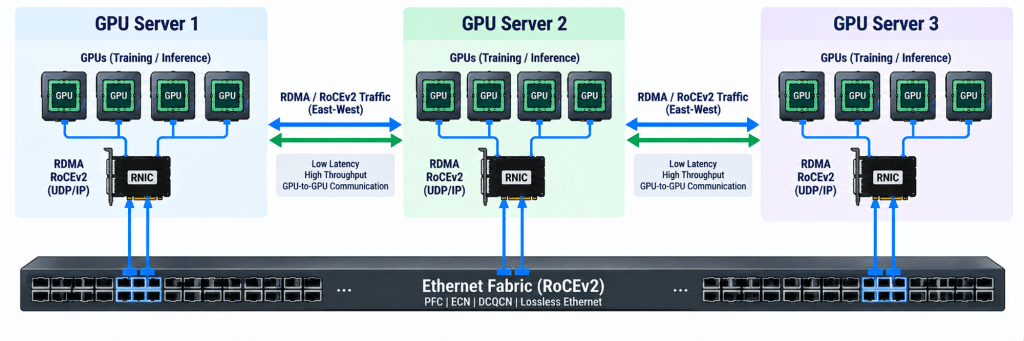
happening behind the application.
This is why I think it is important for infrastructure architects to understand both sides.
The front-end network provides access towards the AI application.
The backend network supports the GPU communication required by the actual model.
Once Tensor Parallelism, Expert Parallelism, Pipeline Parallelism or another form of distributed model execution crosses physical servers, the backend network is no longer simply providing connectivity.
It becomes part of the inference system.
Conclusion
For me RoCEv2 became much easier to understand once I stopped looking at RDMA, PFC, ECN and CNP independently and instead followed the complete journey from the AI workload down to the network.
The AI workload may require parallelism. Parallelism creates GPU-to-GPU communication. Once those GPUs are located across different physical servers, that communication needs to traverse the backend network.
RDMA provides an efficient low-latency method of transferring this data.
InfiniBand has RDMA native to its architecture.
RoCEv2 allows us to transport RDMA across Ethernet.
However Ethernet is fundamentally based around best-effort forwarding, therefore we need additional mechanisms to make it suitable for the low-loss requirements of RDMA.
ECN detects and signals congestion before packet loss occurs. CNP informs the source RNIC about that congestion. The sender subsequently reduces its transmission rate. If congestion becomes severe enough that the queue approaches exhaustion, PFC XOFF temporarily pauses the affected priority and PFC XON allows it to resume once the queue has drained.
The key component to remember here is that RoCEv2 is not simply about enabling RDMA over Ethernet. The complete solution is about controlling how the Ethernet fabric behaves when congestion occurs.
Personally this is why I always find implementation and lab work extremely important. Reading what PFC or ECN stands for gives us the theory. Following the complete packet journey and actually seeing how the technologies interact gives us the understanding.
Once you can explain why the GPU is communicating, why RDMA is required, why normal Ethernet behaviour is not ideal and exactly what ECN, CNP and PFC are doing when congestion occurs, the whole RoCEv2 architecture starts to become much easier to understand.