In my last blog, we discussed what RoCE Ethernet is, how it differs from standard Ethernet, and the primary components involved. In this blog, we will dive deeper into what makes an Ethernet fabric suitable for RoCE by looking at how those components actually work. More specifically, we will follow the messages exchanged between switches and network adapters when congestion occurs.
RoCE stands for RDMA over Converged Ethernet. It allows RDMA communication to operate over Ethernet, with RoCEv2 adding IP and UDP encapsulation so that traffic can traverse a routed network. The congestion-control mechanisms we discuss here support that communication. Understanding their individual roles helps us understand how the entire fabric behaves.
Let’s approach this from a network professional’s perspective. We will use a GPU workload as our example and follow what the switch detects, what the receiver reports, and how the sender responds.
Where does congestion begin?
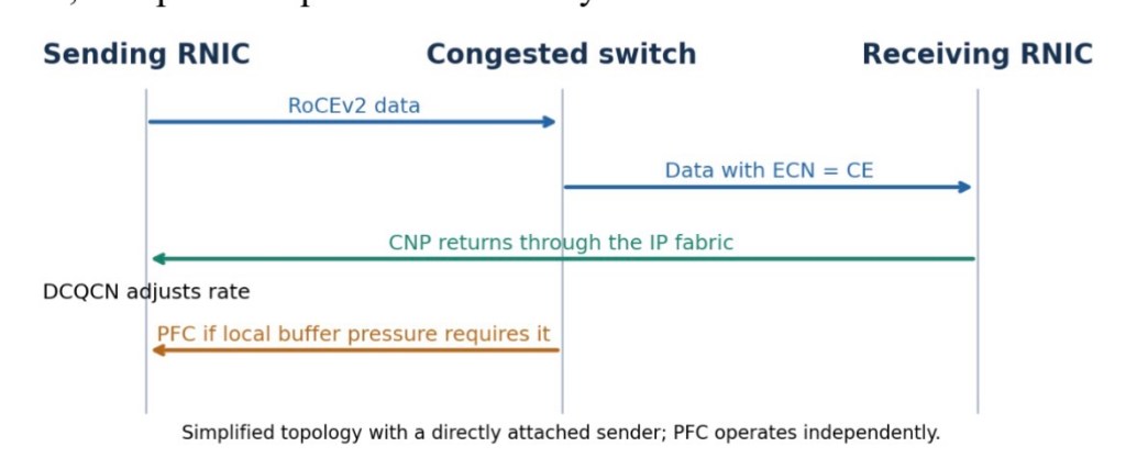
Let’s say several GPU servers are exchanging data during a distributed training job. At a particular point, traffic from multiple servers converges on the same switch output port. If the combined incoming traffic exceeds what that port can transmit, packets accumulate in a queue.
This can happen even when the fabric has sufficient bandwidth overall. The congestion may be concentrated on one output port, or it may be a temporary burst caused by several servers transmitting simultaneously. The workload and its communication pattern determine where that pressure develops.
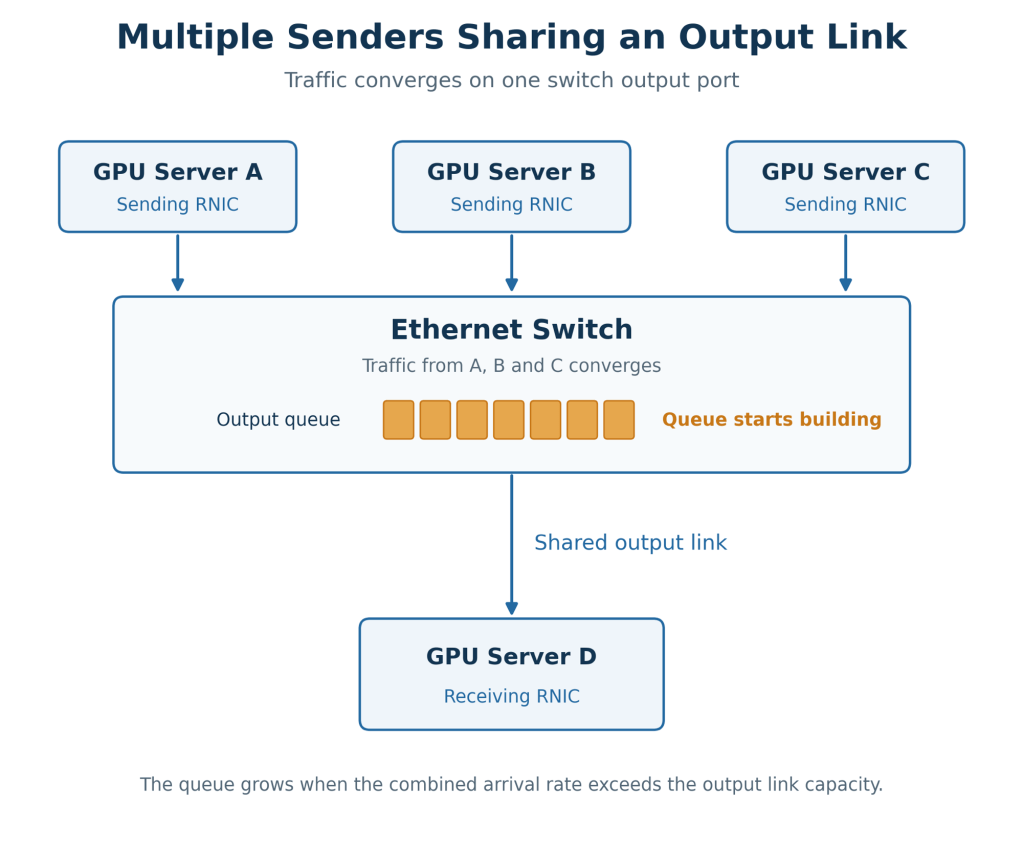
The fabric needs to respond before its buffers run out. In the conventional RoCEv2 design we are following, this involves congestion feedback to the original sender and local flow control between directly connected neighbours. These responses have different scopes, which is important when we get into ECN, CNP, DCQCN and PFC.
ECN – How the switch indicates congestion
Explicit Congestion Notification, or ECN, allows a switch to indicate congestion within the IP header of an eligible packet. When the switch’s configured congestion-marking policy triggers, it changes the packet’s ECN field to Congestion Experienced, or CE. The packet then continues towards the receiver.
Essentially, the switch is marking the data packet that is already passing through it. It does not generate a separate ECN notification packet in this exchange. The message being carried is: “This packet experienced congestion along the network path.”
The ECN field contains two bits:
ECN value Meaning
00 – Not ECN-capable
10 – ECN-capable transport — ECT(0)
01 – ECN-capable transport — ECT(1)
11 – Congestion Experienced — CE
Let’s relate this to our GPU example. Traffic reaches the switch, the output queue starts building, and the marking policy begins marking eligible packets with CE. Those packets still contain the workload’s data, but they now also carry an indication that congestion occurred.
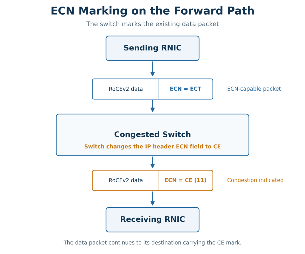
The CE mark does not identify the switch that applied it, describe the queue depth, or tell the sender what transmission rate to use. We still need switch telemetry to locate the bottleneck. ECN gives the receiver an indication of congestion, and the next component provides feedback to the source.
CNP – How the receiver reports congestion
The marked packet reaches the receiving RNIC, which is an RDMA-capable network interface card. In the conventional receiver-generated feedback model, the RNIC detects the CE mark and can generate a Congestion Notification Packet, or CNP.
The CNP is a separate RoCEv2 control packet sent back towards the original sender through the IP fabric. It contains transport identification that allows the sending RNIC to associate the feedback with the affected queue pair, or QP. A queue pair is an RDMA transport context.
The distinction is straightforward: the ECN-marked data packet travels towards the receiver, while the CNP travels back towards the sender. The receiver is effectively reporting that the associated traffic has experienced congestion.
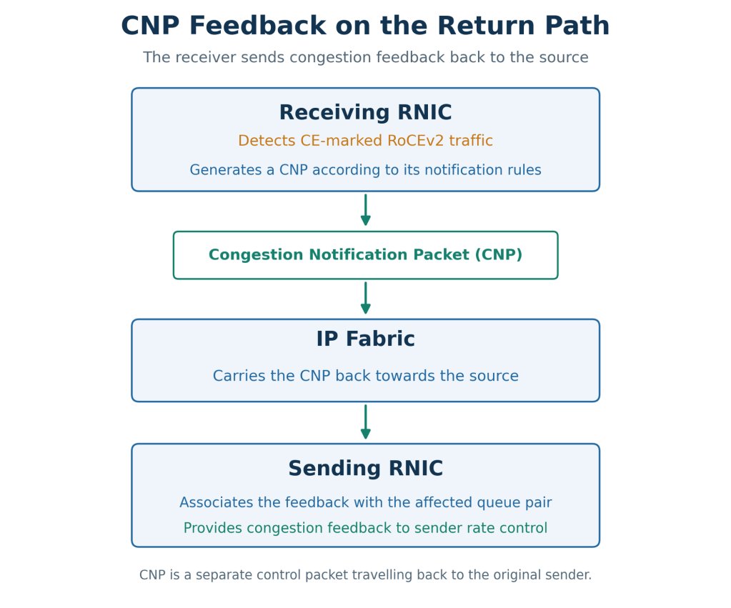
A CNP does not acknowledge successful delivery or request retransmission of lost data. Its role in this exchange is congestion feedback. Also, every marked packet does not necessarily produce an individual CNP. The RNIC’s implementation and notification interval govern how frequently these packets are generated.
From an architecture perspective, the return path matters. If the CNP is delayed, the sender continues transmitting while the feedback is still travelling through the fabric. This is why a design may give CNP traffic a separate queue with preferential treatment.
For example, Cisco’s validated AI networking design uses DSCP 48 for CNP traffic and DSCP 24 for RoCE data, placing CNPs in a strict priority queue. These are choices within that design rather than universal RoCEv2 requirements. We need to validate that the RNIC markings, switch classification and queue mappings agree across the path.
DCQCN – How the sender responds
Once the CNP reaches the sending RNIC, something needs to act on that feedback. In our example, this is Data Center Quantized Congestion Notification, or DCQCN.
DCQCN is the congestion-control algorithm that adjusts the sending rate. It uses congestion feedback to reduce the rate of the affected traffic and manages how that rate recovers as congestion subsides. Its behaviour includes control state, timers and traffic-dependent adjustments, rather than simply applying one fixed reduction to every notification.
You may see the receiver described as the notification point and the sender as the reaction point. These names reflect their roles: the receiver generates feedback and the sender changes its behaviour.
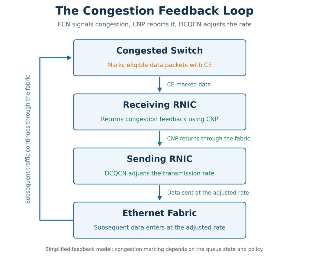
There is no additional “DCQCN packet” after the CNP. The response happens within the sending RNIC’s rate-control behaviour. To validate that response, we need to inspect transmission rates alongside the RNIC’s congestion-control counters.
So far, we have followed the complete feedback exchange. The switch marks the data packet, the receiver reports congestion, and the sender adjusts its rate. However, that exchange takes time, and local buffers may still need protection while it operates.
PFC – How a device asks its neighbour to pause
Priority-based Flow Control, or PFC, operates between directly connected Ethernet neighbours. When receive-buffer pressure reaches the configured threshold for a protected priority, the device sends an Ethernet MAC Control frame to the neighbour transmitting that traffic towards it.
The request is specific: “Pause transmission towards me for this priority for this amount of time.” The PFC frame identifies which of the eight priorities it updates and provides per-priority pause times.
Those times are expressed in pause quanta. One quantum is the time required to transmit 512 bits at the link rate, so the actual duration depends on the speed of the link.
Let’s say priority 3 carries our RoCE traffic. A PFC request for priority 3 asks the neighbour to pause traffic mapped to that priority on this link. Other priorities can continue, subject to scheduling and available resources.
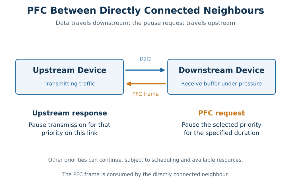
The pause applies to a priority rather than an individual RDMA queue pair. Multiple flows can share that priority, so the pause can affect all of those flows on the link. This is something we need to consider when deciding which traffic should share a protected priority.
Transmission can resume when the pause timer expires or when another PFC frame updates that priority’s pause time to zero. These actions are commonly described as Xoff and Xon: pause and release.
How can PFC backpressure spread?
A PFC frame is consumed by the directly connected neighbour. However, if that neighbour pauses transmission, its own buffers may begin filling. It can then generate a new PFC frame towards its upstream neighbour.
This is how backpressure can spread through the fabric. Each device generates its own local pause request as buffer pressure develops; the original PFC frame is not routed back to the source.
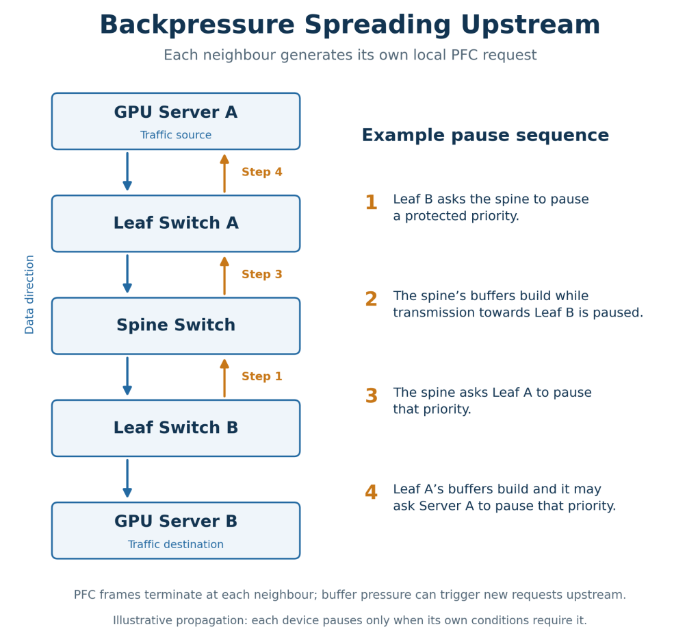
We also need sufficient buffer headroom for packets already in flight while a pause takes effect. Link speed, latency, MTU and device behaviour influence the requirement. A threshold or headroom value that works on one platform should not simply be copied to another.
How ECN and PFC work together
We can now bring the two responses together. ECN provides feedback so the original sender can reduce its rate. PFC protects local buffers by pausing an adjacent transmitter for a selected priority.
Both mechanisms operate concurrently. A sudden burst can trigger PFC before the ECN and CNP feedback loop has time to reduce incoming traffic. PFC does not wait for that exchange to finish.
From a design perspective, we also need to understand where the thresholds apply. ECN marking and PFC triggering can use different egress and ingress buffer resources. We should understand the platform before comparing them as though they were two thresholds on the same queue.
The aim is to control congestion while maintaining useful throughput. Persistent pauses deserve investigation because backpressure can affect additional traffic sharing the same priority.
ETS – How bandwidth is shared between traffic classes
Alongside congestion signalling, the port needs to decide how to share transmission bandwidth. Enhanced Transmission Selection, or ETS, provides scheduling between traffic classes and can allow unused bandwidth from one class to be used by others.
For example, allocating a share of bandwidth to the RoCE class influences how it competes with other traffic on the port. This is local scheduling behaviour; it does not send a congestion notification to a remote RNIC.
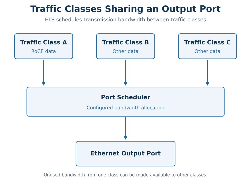
We need to consider this bandwidth allocation alongside any strict priority treatment used for control traffic such as CNPs. Classification and scheduling determine whether the intended policy is actually applied.
DCBX — How neighbours exchange their settings
Data Center Bridging Exchange, or DCBX, carries information within LLDP messages. It uses type-length-value fields, or TLVs, to advertise information such as PFC capabilities, ETS configuration and application priority information.
Depending on the devices’ capabilities and willingness settings, this exchange can help align their behaviour. It exchanges configuration information rather than responding to each congestion event.
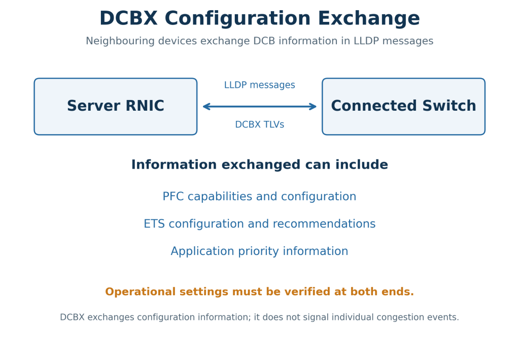
DCBX helps support consistent behaviour between neighbours, but we should still validate the resulting operational settings. Exchanging configuration information does not by itself prove that traffic is classified or handled as intended.
Bringing this back to troubleshooting
Let’s say a training job slows down. We see ECN marking counters increasing on a switch and CNP counters increasing at the receiver. This tells us congestion is being signalled, but it does not yet identify the bottleneck or confirm that the sender is responding correctly.
I would follow the same exchange we have covered in this blog:
- Identify the queue that is building.
- Confirm that marked packets reach the receiver.
- Check that CNPs return to the source.
- Verify that the sending RNIC adjusts its rate.
- Correlate this with PFC pause duration, packet drops and application throughput.
With PFC counters, the direction is particularly useful. Transmitted PFC means “I asked my neighbour to pause.” Received PFC means “My neighbour asked me to pause.” Understanding that direction helps us trace where backpressure started.
Increasing CNP counters can indicate that feedback is working. Persistent PFC pauses need closer investigation, particularly when other traffic shares the affected priority. Compare counter changes over the same time window and relate them to the workload. Lifetime totals alone will not explain why a training job became slower.
For me, this is where understanding the messages adds practical value. We can follow what the switch detected, what the receiver reported and how the sender responded. That gives us a clearer way to design, validate and troubleshoot the Ethernet fabric supporting the AI workload.
References
- Cisco — Validated Design for Data Center Networking for AI/ML
- Cisco — RoCE Storage Implementation over NX-OS VXLAN Fabrics
- Zhu et al. — Congestion Control for Large-Scale RDMA Deployments
- IETF — RFC 3168: Explicit Congestion Notification to IP
- NVIDIA — Priority Flow Control
- NVIDIA — Ethernet QoS
- NVIDIA — LLDP and DCBX




Leave a Reply