
Introduction
In traditional networking Inside our router or multilayer switch there is a separation of duties. In order to fully understand these different duties one needs to understand, what happens when a packet enters our ingress and exits the egress interfaces? We must also get a dynamic overview between forwarding and routing.
However before we delve into the separation of duties within a layer 3 device(e.g router, multilayer switch). We must have a comprehensive dynamic overview of a layer 3 and a layer 2 device lifecycle.
Please note: for the purpose of this article when I refer to a layer 2 devices I am actually referring to a layer 2 switch and a layer 3 device is a router or a multilayer switch
The main differences between a layer 2 and layer 3 devices:
- Layer 2
- Switch frames Within a VLAN
- No alterations to passing data link frame header(Except VLAN tagging on interfaces)
- Layer 2 Filtering(MAC Layer 2 ACL)
- Layer 3
- Switch frames Within a VLAN
- Route packets between different VLANs and subnets
- MultiLayer filtering(ACL filtering based on layer 2, layer 3 and layer 4)
Now to expand on the bullet points above. It’s very clear that a layer 2 device can only switch(forward) frames within a VLAN. It can also perform filtering based on Layer 2 Access control list.
However our layer 3 device, we can forward traffic within VLAN and most importantly it can move packets to different VLAN/subnet this is routing. It can also perform access control list based on layer 3 or layer 4.
Both layer 2 and layer 3 devices can perform forwarding however the layer 3 device is capable of routing to different subnets. The key component is forwarding on a layer 3 device occurs when the source address IP on packet header is in completely different subnet than the destination. Welcome to the separation of duties, routing is performed by the control plane and forwarding is performed by the data plane.
The Layer 2 device
1. The switch receives a frame from one of its interfaces/ports. it will verify the frame header checksum to check if it’s corrupted.
2. The MAC address table of switch is updated with source MAC address of the incoming frame. It will also update the MAC address table with the port/interface that the frame entered from. This will update the MAC table with the ingress physical port and source MAC address of the frame header.
3. The layer 2 switch will forward the frame to the destination MAC on the frame header, this is done by forwarding the frame to the associated port/interface on the switch. If the MAC address table on the switch does not contain the MAC to port/interface adjacency for the incoming frames destination, it will proceed with an ARP broadcast. This will flood all ports/interfaces on the switch except the port that had the incoming frame.
Basic Network+/CCNA stuff, correct?
The Layer 3 device
On layer 3 device IP packet forwarding is based on destination IP.
1. The Layer 3 node receives the incoming packet which contains its own MAC in the destination field of frame.
2. The layer 3 device will perform checksum to verify the frame isn’t corrupted.
3. The layer 3 device will verify checksum to verify the IP packet isn’t corrupted.
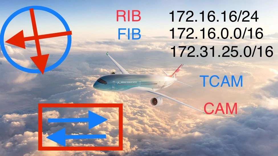
4. The layer 3 device will perform routing table look-up. It will check if the Destination IP is a directly connected or third party subnet in order to route. (For the sake of this example let’s assume it needs to be routed)
5. It will perform the longest-match algorithm and calculate the egress IP address connected to the layer 3 device which is the longest-match
6. It will perform a FIB(forwarding) lookup to determine next hop IP address and interface(e.g int g0/1)
7. Now that the layer 3 node determined the next hop interface. We still can’t forward the frame as we don’t have the correct layer 2 details of the egress interface. The router will require this information in order to amend the Ethernet frame’s destination field.
8. At this stage the layer 3 node will perform adjacency table lookup, specifically the TCAM table. The layer 3 device will obtain the MAC address of next hop interface.
9. It will change the destination MAC field of the frame with the recently obtained MAC of the next hop. It will also amend the source MAC field of frame.
10. It will need to change the IP headers TTL(time to live)field by -1. And because of this, the IP headers checksum will need to be recalculated.
11. The layer 3 device will need to perform recalculation on checksum of the frame, because of the amendment.
12. The frame carrying the IP packet payload will then be forwarded and sent out of the layer 3 device’s interface.
As you can see the the layer 3 node will need to perform a lot more than our layer 2 device….
This is performed by two components in our layer 3 node. The control plane and the Data Plane. They are separated by duties. They divide the above workload between them, however they work as a team.
Introducing The Planes
The control plane is the logic that’s utilised to determine how packets/frames forwarded in the network fabric. Whilst on the other hand the data plane performs the actual forwarding of packets/frames from one interface to another on a layer 3 device….more will be discussed on the planes in Part 2.
Closing thoughts
In my personal opinion It is fundamental to understand the control and data plane of a layer 3 device in order to fully comprehend how packets transverses through a network fabric. Once one fully understands the planes functions you can visualise and gain a dynamic visualisation of how packets are routed across networks and how they are forwarded.
To be continued on Part 2….


Leave a comment