
From the initial hello packet to the empty database descriptor packet and the last Acknowledgment packet.
I prefer not to delve into the specifics of OSPF packets. Instead, my objective is to provide a comprehensive overview of the entire process that unfolds once OSPF is activated on an interface. This includes elucidating each subsequent phase in a clear and chronological manner, offering a thorough understanding of the sequence of events following OSPF activation.
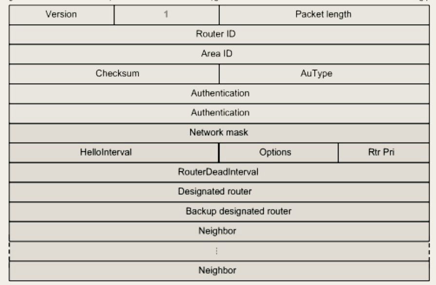
Phase 1: The hello packet
1. Once OSPF is enabled on a routers interface, a Link State Database(LSD) is established and all interfaces running OSPF are added to this table, and will be used in Link State Advertisement.
2. Then the discover and adjacency forming process is initiated. Hello packets are sent and received by neighbouring routers. By default the hello packet advertisement is sent through 224.0.0.5 multicast
3. Hello messages that establish ospf neighbour adjacency contain a list of information :
⁃ OSPF router ID(this is generated manually or automatically)
⁃ Hello interval timer(frequency which the hello message is sent)
⁃ Dead interval timer(how long the router must wait for hello before it declares the neighbour router dead)
⁃ Subnet Mask
⁃ Router priority(used to determine the DR router)
⁃ Area ID
⁃ DR and BDR address(if they exist)
⁃ Authentication password(if configured)
Router 1 sends an initial OSPF Hello packet. Router 2 responds with an OSPF Reply Hello packet.
4. Once a neighbour router receives the hello packet – It runs a check of the above. The following conditions must be met to form a relationship:
⁃ They must have the same IP network/subnet
⁃ The Hello and Dead Interval timers must be identical
⁃ Router interfaces connecting two routers must have the same Area ID
⁃ Type of area must be identical (normal or stub area)
⁃ Authentication password (if used) must be identical
5. If there’s mismatch on any of those fields the R2 on the topology will keep flapping.
6. When R2 receives hello message and there’s a match:
⁃ If R2 is already in a neighbouring router R1 will use it as keep alive message and resets the dead timer, R1 reply will act as a keep alive
⁃ If neighbouring R2 is not listed as neighbouring router to R1. R1 will add it to its neighbour database. All further hello messages will act as keep alive message.
Phase 2 : The empty DBD Packet
Establishing Master-Slave relationship
1. A master/slave router (election process) hierarchy is established after relationship is formed after the hello packets exchange. The purpose of a master/slave is to establish which router will initially send the Database descriptor DBD packet first. Slave/Master router election is completely unrelated to DR or BDR. This slave and master election process is further documented in the IETF rfc2328 https://datatracker.ietf.org/doc/html/rfc2328#page-100
2. In the Master/Slave election process, the router with the highest ID(this can be configured manually)will become the master.
3. Master/Slave Election conditions:
⁃ a) the receiving DBD packets are empty and the (I), (MS) and the (M) bits are set to “1”. This usually is a result of the neighbouring router ID being higher than the recipient router ID consequently The recipient router will become a slave.
⁃ b) the receiving DBD packets are empty and the (I), (MS) and the (M) bits are set to “0”. This usually is a result of receiving routers ID being higher than the neighbouring router that sent the DBD packet, in this case the receiving router will become the master.
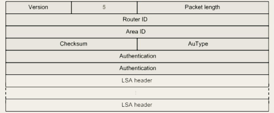
Phase 3. The real DBD packet
1. Now that we have established which router will be master and which will be slave the Third stage of OSPF begins. The master will send the first non-empty DBD packet to the slave.
2. MS(master/slave)field in the OSPF packet will be set to one 1, When the originator is the Master. DPD packets can be more than a single packet subsequently the (M) bit on the packet is set “1” to notify the neighbouring(recipient) router that (M)more packets will be sent. If it’s the last DPB packet the (M) will be set to “0”. The I(initial) bit in the packet will also be set to 1 if the packet is the initial(first) DBD packet, in a series of packets. Subsequent packets will have this I bit set to 0.
3. It’s important to note the crucial payload of DBD packet is the LSA headers. Remember when OSPF is enabled on an interface a link state database(LSD) is established on the local router.The LSA header in the DBD packet describes the local router(sending router) database(LSD)
4. Once the recipient receives the DPD packets from the neighbouring router, the DPD packet recipient router can compare its own database to see if it has an updated database (LSD).

Phase 4: The LSU Packet
1. Once the router determines that some data received in DPD packet’s LSA header payload isn’t in its database it will determine that it doesn’t have an up to date database. The receiving router will make a request for a full LSA, in order to do it will perform Link State Request (LSR) .
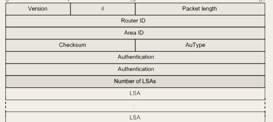
Phase 5: The LSU Packet (LSA PAYLOAD)
1. The neighbouring router responds to the Link state request (LSR) with a Links State Update (LSU). The LSU Packet contains contains full single or multiple LSA’s. In fact the LSU packets are used to flood LSA’s to neighbouring routers, it’s also used to respond to Link State Request LSR.

LSA Packets are encapsulated within LSU packets. In other words LSA are a payload of LSU packets.
LSA payload size can vary depending on the type. LSA’s are what advertise adjacency between adjacency OSPF routers. Different LSA type are generated by OSPF to describe different types of networks by OSPF routers.
Phase 6: LSAck The acknowledgment Packet
1 . The LSAck packet in OSPF is used to acknowledge the receipt of Link State Advertisement (LSA) payload within the LSU packets. When a router receives an LSU packet from a neighbor, it sends an LSAck packet back to confirm receipt. This helps synchronization of routing information within the OSPF Links state Database.


Leave a comment